Internet CHONK
Goals for this section
Let's use the tools and processes we've already discovered to make a much larger internet! In this case, we'll want to be able to traverse several networks to get machines who are not directly connected to communicate with each other. Looking at the network diagram below, we can see that the client machine is connected to the 10.5.0.0/16 network. We want client to be able to traverse our internet to reach server connected to 10.1.0.0/16.
Here's what we expect the internet to look like at the end of this chapter:
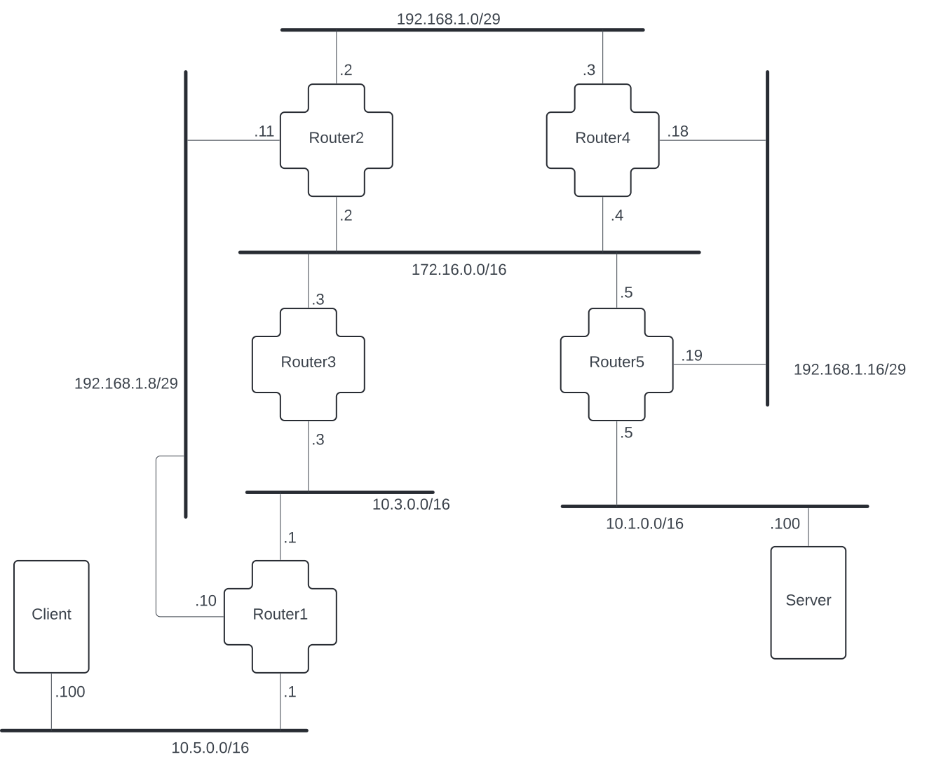
If this network map is a bit challenging to read, take a moment to review the How to Read a Network Map document.
There and Back Again - a setup journey
In order for our little internet to work, we need a way for the machines on our networks to know how and where to route packets. Each router on the network will have a definition of all other networks on the internet and how it can reach machines on those networks. Think about it like this: when a driver is navigating our interstate highways to try to get from Portland to San Francisco, they're gonna see signs that direct them which lanes of traffic will take them in right direction. The driver follows those signs and ends up eventually in the right city. Our routers need those same little signs to follow. Each router will have a "routing table", which is like a list of all our little signs. These routing tables will have entries for how to send packets to each network on our internet.
We want to create routing tables for each of the routers on the network we have diagrammed at the top of this chapter. Each router will need to have entries on how to get to networks that the router does not already have a direct connection to. And, we need these routing tables to be defined as soon as we boot up our network.
In previous chapters, we logged onto the individual routers and manually added routes. In the real world, there are many problems with this approach. We want to be able to write a config where we can see all of our routes at once and, if we restart our internet, we don't lose every route.
In the previous chapter, we introduced the start-up.sh script. Let's open that init/start-up.sh file again for this chapter and define all of the routes that are necessary for router1.
Based on that diagram, out of the 7 networks we've built, router1 already has interfaces on 3 of them:
10.5.0.0/16192.168.1.8/2910.3.0.0/16
So, for router1 to participate in this internet, it needs to know how to route packets to each of the 4 networks it's not currently connected to. We can add routes for each of the 4 networks in our start-up.sh file. We'll use a similar structure to what we used in chapter 2.
So, we'll start by defining how router1 can reach each network through its connections with other routers. You'll see the following already defined in the start-up.sh file for this chapter:
case $HOSTNAME in
  (router1)
    ip route add 10.1.0.0/16 via 10.3.3.1
    ip route add 172.16.0.0/16 via 10.3.3.1
    ip route add 192.168.1.0/29 via 192.168.1.11
    ip route add 192.168.1.16/29 via 10.3.3.1
    ;;
esac
Exercise time: Build your routing tables
The start-up.sh file already has some setup in it. Build out the routes for router3 similar to how you see the routes for router1 being done. Once you've got the routes created in start-up.sh, byoi-rebuild your little internet and hopon router3. Can you ping router1 with ping 10.5.1.1 -w 4? What about if we try to ping router1 with packets that originate from router3 on 172.16.0.0/16? Try using ping -I 172.16.3.1 10.5.1.1 -w 4 to do this.
At this point, router3 knows how to send packets into 10.5.0.0/16, but client doesn't know how to respond. If we try to ping client before we add routes telling client how to reach 10.3.0.0/16, client will just drop those packets. Let's see what that looks like in reality:
root@router3:/# ping 10.5.0.100 -w 2
PING 10.5.0.100 (10.5.0.100) 56(84) bytes of data.

--- 10.5.0.100 ping statistics ---
2 packets transmitted, 0 received, 100% packet loss, time 1031ms
Here, we can see router3 attempting to ping client at 10.5.0.100. There are no response packets received and the ping times out after 2 seconds (the -w 2). Now let's see what's happening on our client, we can watch for those incoming pings with a tcpdump:
root@client:/# tcpdump -ne
tcpdump: verbose output suppressed, use -v[v]... for full protocol decode
listening on eth0, link-type EN10MB (Ethernet), snapshot length 262144 bytes
18:12:02.367255 02:42:0a:05:01:01 > 02:42:0a:05:00:64, ethertype IPv4 (0x0800), length 98: 10.3.3.1 > 10.5.0.100: ICMP echo request, id 25, seq 1, length 64
18:12:03.398455 02:42:0a:05:01:01 > 02:42:0a:05:00:64, ethertype IPv4 (0x0800), length 98: 10.3.3.1 > 10.5.0.100: ICMP echo request, id 25, seq 2, length 64
^C
2 packets captured
2 packets received by filter
0 packets dropped by kernel
There are 2 ICMP echo requests, but we don't see any ICMP echo replys. Set up the route for client to know how to send packets to 10.3.0.0/16 in start-up.sh. Once that's set up, byoi-rebuild, and can you get router3 to ping client? If it's successful, you should see the echo replys on the tcpdump in your client. Let's look at that tcpdump in a bit of detail:
root@client:/# tcpdump -ne
tcpdump: verbose output suppressed, use -v[v]... for full protocol decode
listening on eth0, link-type EN10MB (Ethernet), snapshot length 262144 bytes
21:56:39.729691 02:42:0a:05:01:01 > ff:ff:ff:ff:ff:ff, ethertype ARP (0x0806), length 42: Request who-has 10.5.0.100 tell 10.5.1.1, length 28
21:56:39.729753 02:42:0a:05:00:64 > 02:42:0a:05:01:01, ethertype ARP (0x0806), length 42: Reply 10.5.0.100 is-at 02:42:0a:05:00:64, length 28
21:56:39.729769 02:42:0a:05:01:01 > 02:42:0a:05:00:64, ethertype IPv4 (0x0800), length 98: 10.3.3.1 > 10.5.0.100: ICMP echo request, id 109, seq 1, length 64
21:56:39.730068 02:42:0a:05:00:64 > 02:42:0a:05:01:01, ethertype IPv4 (0x0800), length 98: 10.5.0.100 > 10.3.3.1: ICMP echo reply, id 109, seq 1, length 64
21:56:40.733744 02:42:0a:05:01:01 > 02:42:0a:05:00:64, ethertype IPv4 (0x0800), length 98: 10.3.3.1 > 10.5.0.100: ICMP echo request, id 109, seq 2, length 64
21:56:40.733771 02:42:0a:05:00:64 > 02:42:0a:05:01:01, ethertype IPv4 (0x0800), length 98: 10.5.0.100 > 10.3.3.1: ICMP echo reply, id 109, seq 2, length 64
^C
6 packets captured
6 packets received by filter
0 packets dropped by kernel
The first 2 packets in our tcpdump are ARP packets, i.e. Request who-has 10.5.0.100 tell 10.5.1.1 and Reply 10.5.0.100 is-at 02:42:0a:05:00:64. This is a machine on our network attempting to associate a MAC address with an IP address that it has learned about from an incoming request. For more details on what's happening here, check out the appendix doc on IP and MAC addresses.
Next we see 2 couplets of ICMP echo request and ICMP echo replys. In these packets, we can see that the IP address of the machine requesting the ping is 10.3.3.1, or router3's interface on 10.3.0.0/16. The destination machine is 10.5.0.100, or client's interface on 10.5.0.0/16. But! This also tells us the MAC addresses that are involved in the direct communication with client. So, when we see 02:42:0a:05:01:01 > 02:42:0a:05:00:64,, we can use what we know about how docker creates MAC addresses and see that router1's interface on 10.5.0.0/16, 02:42:0a:05:01:01, is the interface sending the packets to client, 02:42:0a:05:00:64.
ASIDE: MAC addresses
If you'd like to review what a MAC address is in detail, checkout Appendix: ip-and-mac-addresses.
We've been using this word "interface": what does that mean? If we think in real-world terms, your computer has a card or chip or plug or something that is used to connect it to the Internet. That card/chip thingy has an identifier similar to a serial-number that is burned into its silicon by the company that made it. The general purpose of a serial-number is to identify a specific unit uniquely. For your computer's network interface, that identifier is known as its "Media Access Control" or "MAC" address. Hardware companies that make network interfaces coordinate with each other to ensure that no two MAC addresses are the same throughout the entire world for all of time.
Because this MAC address is used to uniquely identify your computer's network interface, a router can use it to ensure packets get to the correct destination. So when your computer joins a network, it will tell the router responsible for connecting it to the internet its MAC address. If you'll remember from Chapter 1.2, we had a brief aside on ARP (Address Resolution Protocol) which is the system that maps IP addresses to MAC addresses. This way, when packets are routed to and from your computer, the router can translate your computer's IP address to your computer's MAC address so that it can send those packets through your local network to your computer.
The machines we're working with throughout Build Your Own Internet don't have any actual hardware. So when you hopon server or any other machine, you're interacting with a virtualized hardware device and that virtual machine has a virtual MAC address. The software responsible for making that virtual hardware is called Docker, and the way Docker makes MAC addresses is a little unusual. Because there's no actual silicon to burn a MAC address into, Docker has to create that MAC address out of thin air. It seems that Docker has chosen to use the IPv4 address of each interface on a machine to inform its decision on how to create the MAC address on that interface.
For example, let's look at the output for one of our interfaces shown in ip addr:
38: eth0@if39:  mtu 1500 qdisc noqueue state UP group default
    link/ether 02:42:0a:01:02:03 brd ff:ff:ff:ff:ff:ff link-netnsid 0
    inet 10.1.2.3/24 brd 10.1.2.255 scope global eth0
       valid_lft forever preferred_lft forever
Here, we can see that the version-4 IP address of the machine is 10.1.2.3 on a /24 network. The MAC address listed on the line above is 02:42:0a:01:02:03. Docker takes the IP address for that machine and converts it to hexidecimal. So in this case, if we look at the end of that MAC address, 0a:01:02:03, and we convert it from hexidecimal into decimal, we get 10.1.2.3. This is great for us because it means that when we look at MAC addresses in our tcpdump output, it is much easier to correlate them to the machine associated with that IP address.
📝 NOTE: When you see ethernet packets in the wild, there is no correlation between the MAC address and the IP address. This is simply a docker convenience.
Back to building routing tables...
Now that you have router3 able to ping client, build out the rest of the internet! Check that things work using ping at every step of the way! We recommend building out one "hop" at a time, so from router3, build out router2's connections. Check that router2 can ping client and router5. Move to router4. Can it ping client, router3, router5, and router2? Can it ping each router on every interface that router has on any network?
If you have problems creating your routing tables, the next exercise is going to cover troubleshooting!
Exercise 2: Understanding and diagnosing routing problems on your internet
Here's a handy flowchart to help you understand the output you see in your terminal from a ping command:
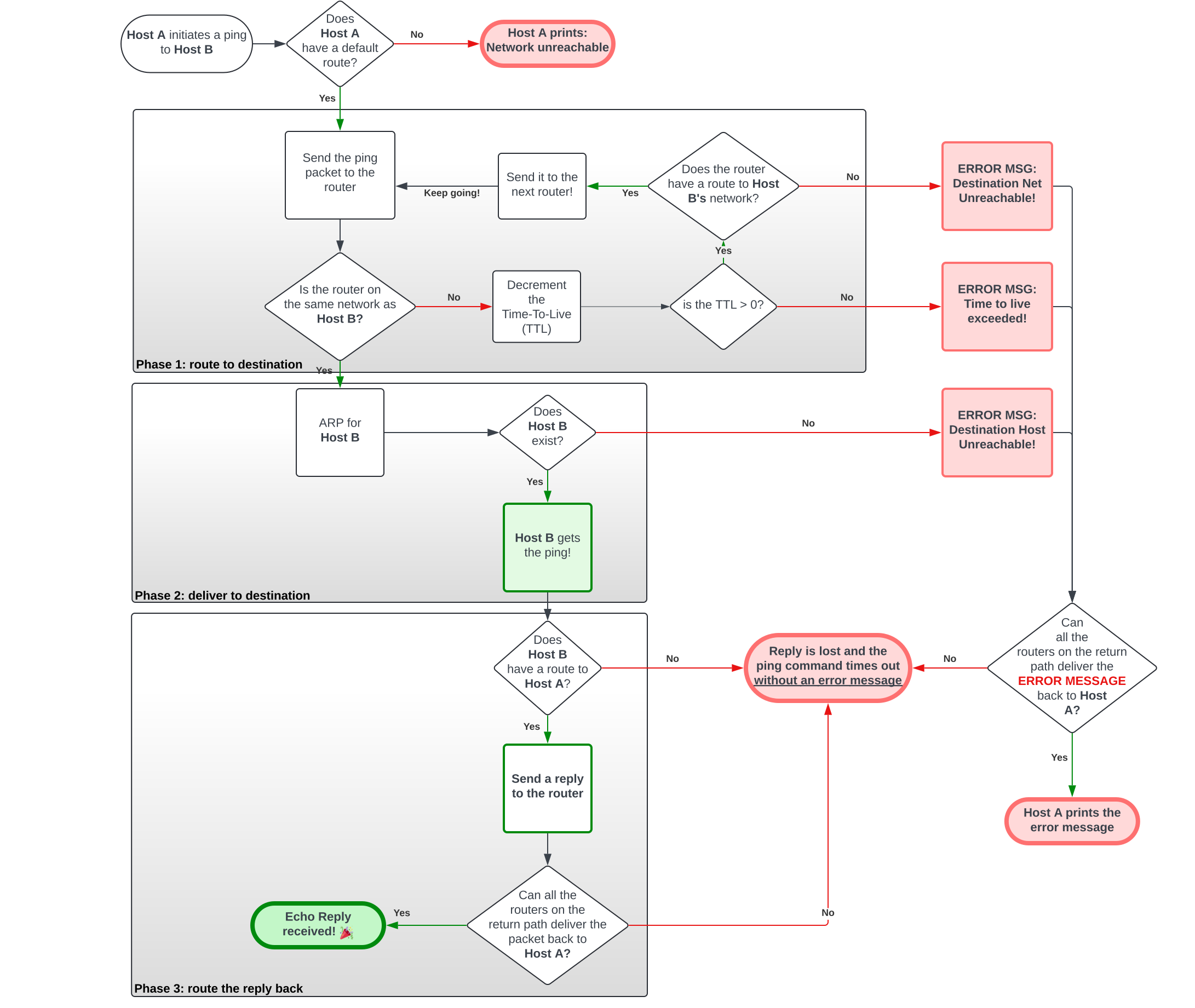
Basically, when you run a ping, there are three potential outputs you will see in your terminal:
- A successful response
- An error message (a few different varieties of these)
- No output
A successful response should look familiar to you from all the work we've done so far. It indicates that a packet can successfully make a round-trip from your machine to the destination and back again. We're not going to dive into this.
When you get an error message, you may see one of these:
Network unreachable: your machine doesn't even know where to start sending the packet.Destination net unreachable: some router on the way to the destination doesn't know how to reach the destination network.Destination host unreachable: a router connected to the destination network told us that there is no machine there by that address.Time to live exceeded: this probably means we have a routing loop. We'll cover that in the next section 😘.
All of these are error messages are on the route to the destination. If you get an error message, this means that there's something wrong with the path going to the destination machine. The message on your screen will include the IP address of the router that generated the error message. This tells us two things: (1) where to look for the error, and (2) since the error message got back to you, you know that the network can deliver packets to and from the router that's reporting the error.
When you get no output, this means that response packets to your machine were lost somewhere on the way back to your machine. The response packets could have been an error message like we saw above or a reply message from the destination. This is harder to troubleshoot because we don't know where the packets are getting lost.
💡 POP QUIZ!:
hopon clientand try each of these pings. If you get an error message, provide an explanation for which machine generated the error message and why:
ping 10.3.1.10ping 10.9.0.1
Exercise 3: A nastier break
We've built an internet! Yay! But this is a fairly small internet and maybe you got everything right the first time. People rarely learn from things going right… SO! Let's see what happens when we have broken routing tables on our Internet and we have to find the problem. Let's set up your environment with a break so you can investigate along with us.
Set up your environment
The first thing we'll need to do is get your network set up with a break we can investigate! Lucky for you, we've already created a setup that is broken and ready to use.
To start, you're going to run the byoi-rebuild command again.
📝 ASIDE: Whenever you run
byoi-rebuild, it's going to reset the internet. When you run it with a special flag (--exercisein this case), it's going to use different configuration options for the network. If you want to restore the work you did earlier in this chapter, runbyoi-rebuildwithout the flag.
Set up this exercise as follows:
byoi-rebuild --exerciseDiscover the breakage
Let's first see what happens when our client tries to ping our server:
root@client:/# ping -c2 10.1.0.100
PING 10.1.0.100 (10.1.0.100) 56(84) bytes of data.
From 10.3.3.1 icmp_seq=1 Time to live exceeded
From 10.3.3.1 icmp_seq=2 Time to live exceeded

--- 10.1.0.100 ping statistics ---
2 packets transmitted, 0 received, +2 errors, 100% packet loss, time 1022ms
Go back to the flowchart in exercise 2 above. What does this output tell you about the break we currently have? What does "Time To Live" mean??
Time To Live (TTL)
Let's start by looking at the output of a successful ping from client to router1:
root@client:/# ping 10.5.1.1 -w 2
PING 10.5.1.1 (10.5.1.1) 56(84) bytes of data.
64 bytes from 10.5.1.1: icmp_seq=1 ttl=64 time=0.101 ms
64 bytes from 10.5.1.1: icmp_seq=2 ttl=64 time=0.207 ms

--- 10.5.1.1 ping statistics ---
2 packets transmitted, 2 received, 0% packet loss, time 1068ms
rtt min/avg/max/mdev = 0.101/0.154/0.207/0.053 ms
Do you see how, on each response recorded in this example, there's a ttl=64: 64 bytes from 10.5.1.1: icmp_seq=1 ttl=64 time=0.101 ms? OK, let's jump out one hop and look at the output for a ping to router3:
root@server:/# ping 10.3.3.1 -w 2
PING 10.3.3.1 (10.3.3.1) 56(84) bytes of data.
64 bytes from 10.3.3.1: icmp_seq=1 ttl=63 time=0.181 ms
64 bytes from 10.3.3.1: icmp_seq=2 ttl=63 time=0.480 ms

--- 10.3.3.1 ping statistics ---
2 packets transmitted, 2 received, 0% packet loss, time 1028ms
rtt min/avg/max/mdev = 0.181/0.330/0.480/0.149 ms
Oooh! In this case, it's ttl=63. ping uses ttl, or "time to live", not by counting seconds, but instead by counting hops. So, when a ping is newly generated, it has its ttl set to a default number. Different operating systems have different defaults defined. On the linux system we are using in our containers, the default appears to be 64. You can confirm that by running the following:
root@client:/# cat /proc/sys/net/ipv4/ip_default_ttlWhenever a router receives an IP packet, it decrements this count. Before forwarding the packet, the router will check to see if the ttl is still greater than 0. If the ttl has reached 0, then the router will decide that the request has timed out (or in the words of the error, Time to live exceeded).
🤔 Hmm. But our network is still pretty small. How could it be that a packet could have traversed 64 different routers on its way to its destination?
The only way we could have exceeded the 64 count ttl in our little network is if we have a routing loop. A routing loop takes place when two or more routers have their routing tables set up in such a way that they send packets back and forth to each other without ever making progress toward the packet's destination.
Dope! Now we know for sure that the problem is a routing loop and that it exists on the request path! The other thing we see in that error in our ping is that the router that issued the timeout: 10.3.3.1 or router3. Let's hopon router3 and issue a ping to server and see if it gets there.
The Investigation
We need some process to help us identify where the problem in our internet lives. What we've tried so far is to ping from server to client. That's causing us to traverse our whole internet, which is a lot of machines and a lot of points of potential failure. We can simplify this in a couple ways. First, we can figure out if the issue is in routing the requests TO or FROM the destination IP. Once we know the direction that the packets are getting lost, we can check, hop by hop, where the packets are going and find the exact router(s) where they're getting lost.
Let's start by running that same ping from server to client, but this time, let's watch on client to see if the packets are even making it there. Open a second terminal window and run a tcpdump on client:
root@client:/# tcpdump -n
tcpdump: verbose output suppressed, use -v[v]... for full protocol decode
listening on eth0, link-type EN10MB (Ethernet), snapshot length 262144 bytes
21:31:52.871414 IP 10.1.0.100 > 10.5.0.100: ICMP echo request, id 81, seq 1, length 64
21:31:52.871444 IP 10.5.0.100 > 10.1.0.100: ICMP echo reply, id 81, seq 1, length 64
21:31:52.871718 IP 10.3.3.1 > 10.5.0.100: ICMP time exceeded in-transit, length 92
21:31:53.902288 IP 10.1.0.100 > 10.5.0.100: ICMP echo request, id 81, seq 2, length 64
21:31:53.902331 IP 10.5.0.100 > 10.1.0.100: ICMP echo reply, id 81, seq 2, length 64
21:31:53.905679 IP 10.3.3.1 > 10.5.0.100: ICMP time exceeded in-transit, length 92
Great! We can see the packets coming in from server, 10.1.0.100:
21:31:52.871414 IP 10.1.0.100 > 10.5.0.100: ICMP echo request, id 81, seq 1, length 64
And we can see the response packets going out:
21:31:52.871444 IP 10.5.0.100 > 10.1.0.100: ICMP echo reply, id 81, seq 1, length 64
This means that the routing problem is on the response path back from client => server!
But what's this ICMP time exceeded in-transit?
21:31:52.871718 IP 10.3.3.1 > 10.5.0.100: ICMP time exceeded in-transit, length 92
It appears that router3 on 10.3.0.0/16 is letting the client know that it is unable to route packets.
root@router3:/# ping 10.1.0.100 -w 2
PING 10.1.0.100 (10.1.0.100) 56(84) bytes of data.

--- 10.1.0.100 ping statistics ---
2 packets transmitted, 0 received, 100% packet loss, time 1022ms
But this ping alone won't tell us much. Let's re-run that ping while we watch the traffic on Router3 to see where our requests are going. To start with, we need to know which interface the requests are leaving Router3 on, which means... back to our old friend ip addr:
root@router3:/# ip addr
1: lo:  mtu 65536 qdisc noqueue state UNKNOWN group default qlen 1000
    link/loopback 00:00:00:00:00:00 brd 00:00:00:00:00:00
    inet 127.0.0.1/8 scope host lo
       valid_lft forever preferred_lft forever
777: eth1@if778:  mtu 1500 qdisc noqueue state UP group default
    link/ether 02:42:03:00:03:01 brd ff:ff:ff:ff:ff:ff link-netnsid 0
    inet 10.3.3.1/16 brd 3.255.255.255 scope global eth1
       valid_lft forever preferred_lft forever
791: eth0@if792:  mtu 1500 qdisc noqueue state UP group default
    link/ether 02:42:64:01:03:01 brd ff:ff:ff:ff:ff:ff link-netnsid 0
    inet 172.16.3.1/16 brd 172.16.255.255 scope global eth0
       valid_lft forever preferred_lft forever
Remember, this output could be different on your build of the little internet, so run this for yourself and use the correct interfaces for the network addresses we're watching. In this case, Router3's interface on 10.3.0.0/16 is eth1 and its interface on 172.16.0.0/16 is eth0. Open a new terminal window and run your tcpdump on both. This will tell us which interface the packets are exiting out of:
root@router3:/# tcpdump -nei eth0
tcpdump: verbose output suppressed, use -v[v]... for full protocol decode
listening on eth0, link-type EN10MB (Ethernet), snapshot length 262144 bytes
21:57:59.839787 02:42:64:01:03:01 > 02:42:64:01:02:01, ethertype IPv4 (0x0800), length 98: 172.16.3.1 > 10.1.0.100: ICMP echo request, id 91, seq 1, length 64
21:57:59.839891 02:42:64:01:02:01 > 02:42:64:01:03:01, ethertype IPv4 (0x0800), length 98: 172.16.3.1 > 10.1.0.100: ICMP echo request, id 91, seq 1, length 64
21:58:00.861600 02:42:64:01:03:01 > 02:42:64:01:02:01, ethertype IPv4 (0x0800), length 98: 172.16.3.1 > 10.1.0.100: ICMP echo request, id 91, seq 2, length 64
21:58:00.861768 02:42:64:01:02:01 > 02:42:64:01:03:01, ethertype IPv4 (0x0800), length 126: 172.16.2.1 > 172.16.3.1: ICMP redirect 10.1.0.100 to host 172.16.3.1, length 92
21:58:00.861795 02:42:64:01:02:01 > 02:42:64:01:03:01, ethertype IPv4 (0x0800), length 98: 172.16.3.1 > 10.1.0.100: ICMP echo request, id 91, seq 2, length 64
^C
5 packets captured
5 packets received by filter
0 packets dropped by kernel
There is a lot happening in this output. Let's look at it line by line to understand what is happening.
Let's start with:
21:57:59.839787 02:42:64:01:03:01 > 02:42:64:01:02:01, ethertype IPv4 (0x0800), length 98: 172.16.3.1 > 10.1.0.100: ICMP echo request, id 91, seq 1, length 64.
Here, we see router3 sending a packet destined for server (172.16.3.1 > 10.1.0.100) via router2 (02:42:64:01:03:01 > 02:42:64:01:02:01). We are referencing IP and MAC addresses to glean this information. If this is confusing to you, you can look at Appendix: Understanding tcpdump for more details. This is the basic communication we are expecting to see. ICMP echo request is the initiation of a ping. Referencing our network map, it seems like it is a bad choice to be routing the packet to router2 but we are people that are open to possibilities. So we will remain curious and see what happens!
On to the next line:
21:57:59.839891 02:42:64:01:02:01 > 02:42:64:01:03:01, ethertype IPv4 (0x0800), length 98: 172.16.3.1 > 10.1.0.100: ICMP echo request, id 91, seq 1, length 64
Hmmm, it appears that router2 agrees with our earlier assessment! We see the original source and destination IPs from router3 to server (172.16.3.1 > 10.1.0.100) but router2 is sending the packet back to router3 (02:42:64:01:02:01 > 02:42:64:01:03:01). That's what we in the biz say, "Not cool man!"
We think we might have found the problem: router3 is sending packets to router2 and router2 is returning them in an infinite loop! But let's keep looking at this pitter patter among routers just to see if there is anything more interesting!
21:58:00.861600 02:42:64:01:03:01 > 02:42:64:01:02:01, ethertype IPv4 (0x0800), length 98: 172.16.3.1 > 10.1.0.100: ICMP echo request, id 91, seq 2, length 64
First off, we see seq 2 which is different from seq 1 that we have seen thus far. This tells us that it is the second ping request being sent to server. This is the same pattern we observed in the first ping request, so let's continue on!
21:58:00.861768 02:42:64:01:02:01 > 02:42:64:01:03:01, ethertype IPv4 (0x0800), length 126: 172.16.2.1 > 172.16.3.1: ICMP redirect 10.1.0.100 to host 172.16.3.1, length 92
ICMP redirect! What does that mean? It's the technical term for the pitter patter we were observing earlier. When a router receives packets on the same interface it will forward them out of, that means the machine it received the packets from and the machine it is forwarding the packets to are on the same network. Therefore, they can communicate directly with each other instead of going through the intermediate router.
In our case, router2 is sending a ICMP redirect to router3 so router3 can make a more efficient routing decision and not have packets destined to server go through router2. router3 ignores these messages for two reasons:
- it makes no sense for router3 to send packets to itself to reach
server. - Kernels have a configuration to determine whether to accept ICMP redirects but they are generally disabled for security reasons.
21:58:00.861795 02:42:64:01:02:01 > 02:42:64:01:03:01, ethertype IPv4 (0x0800), length 98: 172.16.3.1 > 10.1.0.100: ICMP echo request, id 91, seq 2, length 64
Finally, we get to our last line... We see the same thing we saw in seq 1; router2 is sending the echo request packets router3 had sent to it right back to router3.
We've found out loop! Next step: go check the start-up-exercise.sh and look at the routes going to 10.1.0.0/16 on both router2 and router3. Where should those point instead? Use the network map at the beginning of this chapter to determine where these packets should be getting forwarded to and update the routes. byoi-rebuild your containers and try your ping again!
Appendix:
Check the ping -h help to see how you can originate your ping from a specific interface. Can you ping from a specific interface on a router to a specific interface on another router?